
A not-so-detailed introduction to graphical pipeline
You can find a number of resources to learn about the details of the graphics pipeline. For computational purposes, and to use the Abubu.js library knowing that level of details may not be necessary and could be actually distracting. Here, we will briefly review a simplified overview of the graphics pipeline that could help you understand the details of the following tutorials.
Rendering
The objects of interest are usually in three dimensional space and they need to be mapped to a two dimensional screen to be displayed on. The process of mapping the three dimensional objects from the 3D world into a 2D screen and coloring the objects is called rendering.
Geometrical primitives
The graphical pipeline mostly deals with three basic geometrical primitives, namely,
- Vertices or points,
- Lines,
- and Triangles.
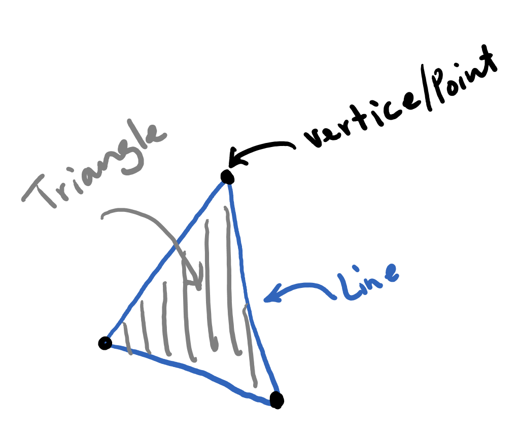
You can connect vertices to construct lines, connect lines to construct triangles. Any surface can be approximately represented using a mesh of triangles.
Rendering in the clip space
The rendering process starts by mapping the coordinates of all the objects to be rendered from the 3D world into a 3D rendering coordinate system. Let's say that our physical coordinates are \(XYZ\). The objects are then mapped to a system with the coordinates \(xyz\).
The clip space is a cube based on which the graphics pipeline decides whether an object will be rendered or ignored. The coordinates of the clip space cube range from \(-1\) to \(1\) (see the figure below).
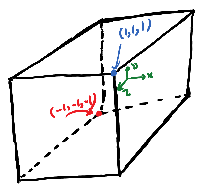
The mapped coordinates \(xyz\) that are inside the cube will be rendered and otherwise they will be ignored.
To map a geometry that is made of the above-mentioned geometrical primitives into the clip-space, it is enough to just map the vertices. The lines can automatically be formed by connecting the vertices, and subsequently, the triangles can be formed by connecting their constructing lines.
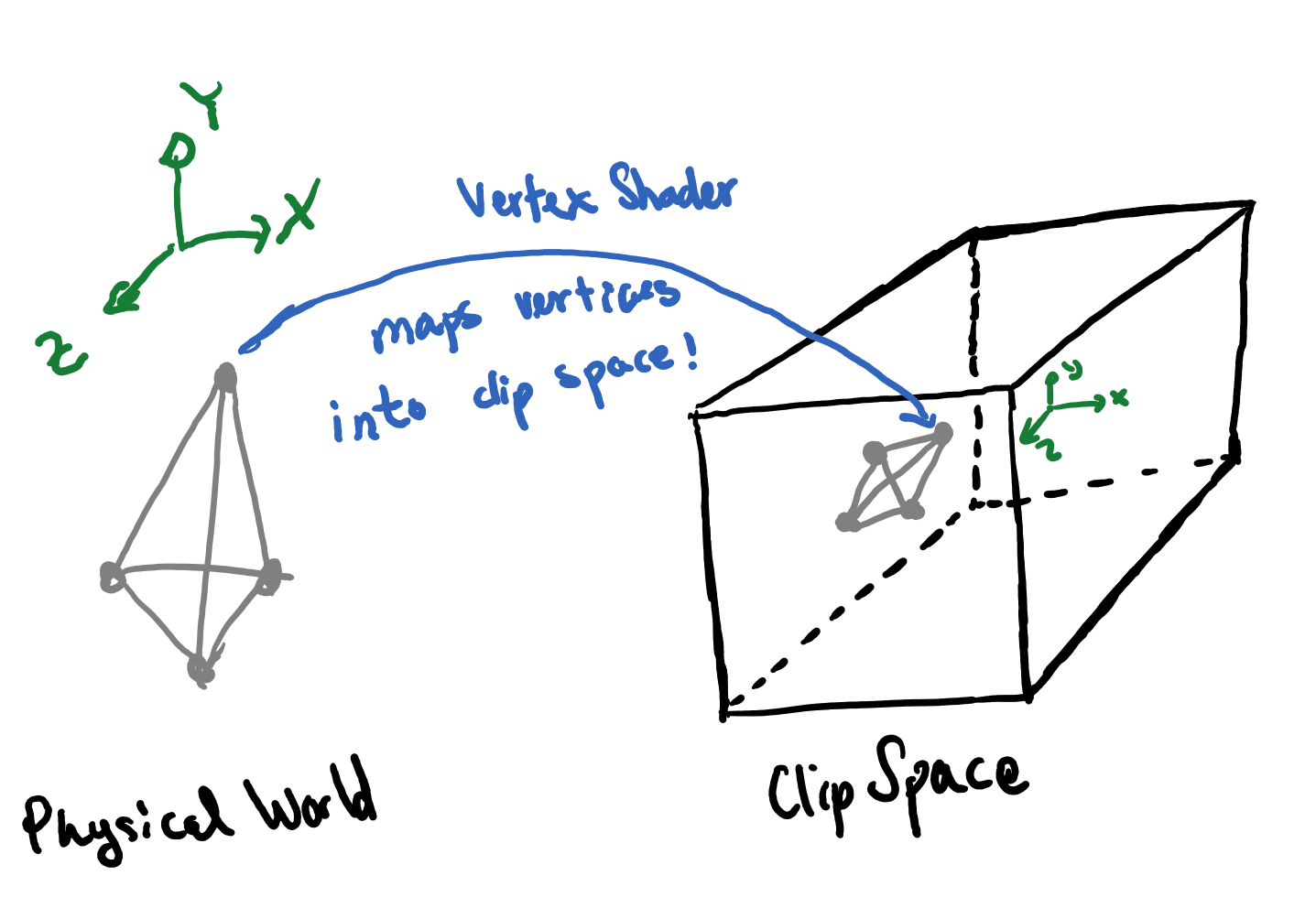
The vertex-shader is part of the pipeline that one of its duties is mapping the coordinates of the vertices from the physical world into the rendering coordinate of the clip space. This is a part that needs to be designed and implemented by the programmer.
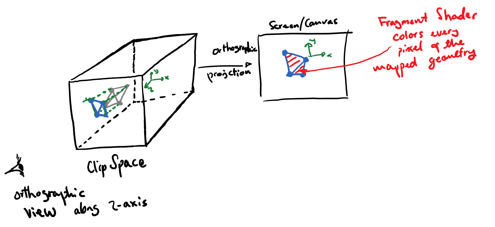
The next step is to employ an orthographic view from the positive side of the \(z\)-axis of the clip-space and along the same axis and map the larger values of \(z\) to the screen and cull (ignore) those coordinates that end up behind (have smaller values of \(z\)). You can see a schematic of the process below.
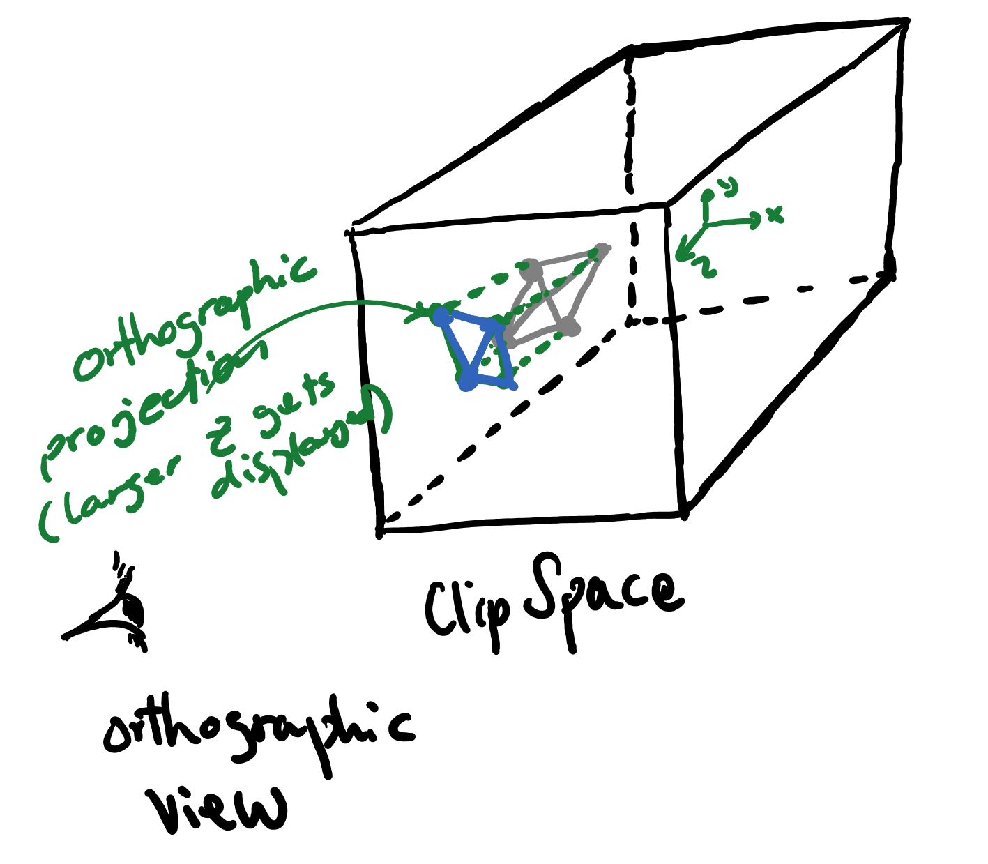
Therefore, our screen will have a coordinate system that is consistent with the picture below:
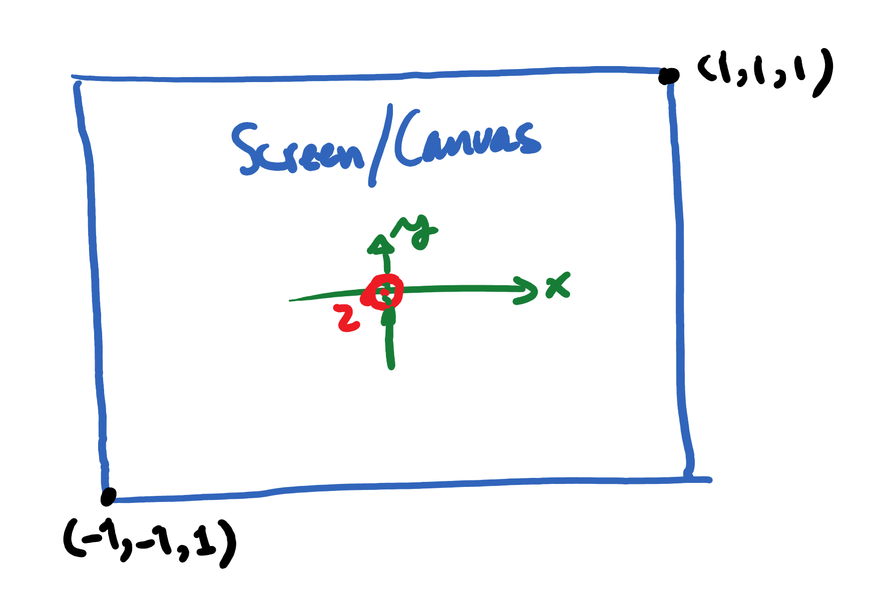
The last step is carried out by a program called fragment shader which will be in charge of coloring every pixel that is on the geometry and is lies within the clip-space.
The next tutorial will provide an example of this process.